ABSTRACT:
Glass fibre filled PA 6 and PA 6.6 are two of the more common materials injection moulded with the MuCell microcellular foaming process. As the technology continues to expand into under the hood applications, the need to understand vibration welding and ultrasonic welding becomes more critical.
This paper will compare welding performance for PA 6 and PA 6.6 moulded as solid and by the MuCell process. It will also discuss weld line strength and variation across test specimens as well as understanding proper welding performance.
INTRODUCTION:
Microcellular foam injection moulding is a technology that has received significant attention over the last 4 to 5 years. The basis of this technology originated in the Mechanical Engineering Department at The Massachusetts Institute of Technology (M.I.T.) the early 1980’s. That work, which was lead by Dr. Nam Suh, forms the basis for the technologies currently available in the market today. As interest has spread, the technology is being used in more applications with varied requirements.
One area of growth is in under the hood applications typically in glass fibre filled PA 6 or PA 6.6 such as fan shrouds, air intake manifolds and rocker covers. These applications lend themselves to the MuCell process because of frequent dimensional issues and overall part mass. Dimensional issues are also a cause for welding problems as this effect the contact pressure between the parts.
Two of the more common welding techniques are ultrasonic for small parts and vibration for larger assemblies. This paper will discuss both methods although vibration welding is the more common for under the hood applications.
TECHNOLOGY FUNDAMENTALS:
The fundamentals of microcellular foam moulding have been covered in many papers and articles including work by M.I.T., Trexel, Sulzer Chemtech and IKV Aachen. As such, we will not go into details here but just provide a basic summary. The concept as it applies to the injection moulding process involves introducing a physical foaming agent, typically nitrogen or carbon dioxide, in the form of a supercritical fluid into a molten polymer. That molten polymer is under the appropriate temperature and pressure conditions to cause the foaming agent to dissolve into the polymer to create a single phase solution. Implied in the term single phase solution is not only that the foaming agent is completely dissolved in to the polymer but that it is also uniformly dispersed throughout the polymer. Once the single phase solution is created, it must be maintained until the material is injected into the mould cavity.
When the single phase solution of foaming agent and polymer is introduced into the mould, it undergoes a thermodynamic change, a pressure drop, which causes cell sites to form (cell nucleation) and then grow as the foaming agent comes out of solution. Cell density, the number of cells for a given volume of material is a function of the amount of foaming agent as a function of its saturation limit and also the rate of pressure drop (change in pressure/time increment). This basic mechanism is applicable to any system using a physical foaming agent to create a microcellular injection moulded part.
WELDING METHODS:
The are a number of welding technologies used in the market today including vibration welding, ultrasonic welding, hot plate welding and spin welding. Of these, vibration welding is the most common for large parts with complex parting lines such as air intake manifolds and is of more interest with microcellular foamed parts as these larger parts typically achieve greater benefits from the MuCell process. In vibration welding, the plastic parts are fixtured in such a manner that the weld surfaces are brought into contact under pressure. The weld surfaces are then rubbed together in either a linear or orbital manner at a given frequency, pressure and time. As the parts move, friction builds, causing the surfaces in contact to melt. Once sufficient material has been melted, the movement between parts stops and the molten plastic at the interface cools and solidifies to form a bond between the parts.
Ultrasonic welding is more common with small parts. In this technique, one part is held stationary while a second part is brought into contact. A high frequency vibration is placed on the moving part causing friction at the contact points which results in a melting of the material at the weld face. Parts being joined by ultrasonic welding typically have a design feature on the weld surface to focus the welding energy.
EXPERIMENTAL:
Two studies were conducted on a 35% glass fibre filled PA 6 and a 35% glass fibre filled PA 6.6. Test specimens produced in standard solid injection moulding and by the MuCell process were evaluated for weld strength when assembled using both ultrasonic welding and vibration welding. The target density reduction for all samples produced by the MuCell process was 10%.
The first study was conducted with Branson Ultrasonics using a test configuration known as a coffin. The coffin mould consists of two parts that when welded together form a box. One of the parts has a hole that can be used to pressure test the welded assembly. The materials used for this study were a TechnylXCell S218V35 (35% glass fibre filled PA 6) and a Technyl A218V35 (35% glass fibre filled PA 6.6). The samples were
ultrasonically welded and the weld strength was evaluated on the assembly first by a pull test and then a pressure test.

Coffin Mould
The same materials were then tested by Rhodia Engineering Plastics using a bell shaped part and vibration welding. This part is such that two are welded together to give a specimen that can be tested for burst strength. The part is designed to focus the failure on the weld and not on the material wall.

Bell Mould
RESULTS and DISCUSSION:
Ultrasonic Welding:
The initial step of the ultrasonic welding study was to establish optimum welding conditions. This is defined as having a full weld across the wall thickness but without weld flash. The welding conditions were optimized by adjusting the welding time to either increase or decrease the amount of molten material created in the weld zone. The suitability of the weld was determined by sectioning assemblies and looking at the weld joint. A good weld does not have flash outside the walls of the part but does have contact the full width of the walls. The results of the optimization for the PA 6 shows a shorter weld time for the parts produced using the MuCell process, 0.195 seconds as compared to 0.275 seconds for solid parts. Since the applied load and frequency were the same, this resulted in lower overall weld energies for the parts produced with the MuCell process.
This was not the case with the PA 6.6. The results of the welding optimization showed that the parts produced with the MuCell process and those produced with standard solid moulding both required the same weld time, 0.200 seconds. This resulted in equal weld energy.
The ultrasonically welded samples were evaluated in two separate test configurations: a pull test and a burst pressure test. The pull test is done using a tensile test system. In this case, the upper and lower flanges of the assembly are placed in fixtures and the specimen is put in tension until the weld fails. The results of this testing show that the weld performance of the PA 6 was better than the PA 6.6. It also indicated that for PA 6, the parts moulded using the MuCell process had a higher average failure load than the solid parts, 37% higher. Using PA 6.6, it was seen that the average results were the same between the solid parts and the parts from the MuCell process. The difficulty with the pull test is that the standard deviation is quite large meaning that there is statistically very little difference between the assemblies made from the solid parts and those from the MuCell process.
Graph 1 – Ultrasonic Welding Pull Data – 10% Density Reduction
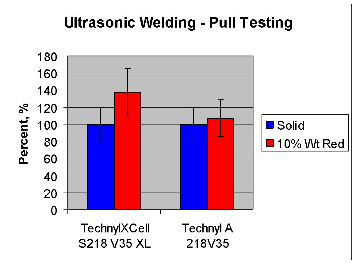
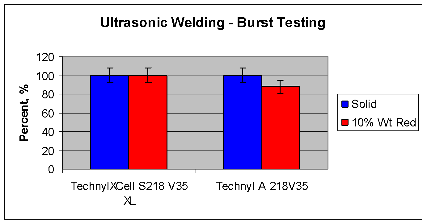
The data from the burst testing are of more value due to the repeatability of the data as well as the fact that it more readily simulates the in use failure condition. The data here show that the PA 6 samples produced from the MuCell process had equal burst performance to the solid samples. There were two observations with the PA 6.6. First as with the pull testing, the burst pressures were lower that those for the PA 6. Secondly, there was a decrease in the burst pressure for the MuCell samples as compared to solid of 12%.
Graph 2 – Ultrasonic Welding Burst Data – 10% Density Reduction
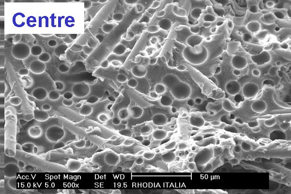
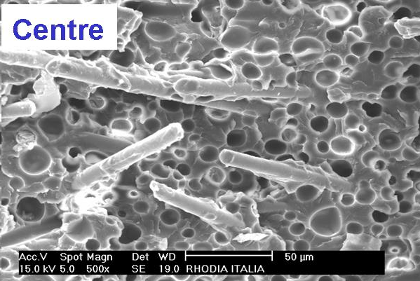
Analysis of the ultrasonically welded MuCell samples shows that the cell structure in the core of the parts moulded with both the PA 6 and the PA 6.6 is similar, less than 20 microns, but the PA 6 samples have a thicker skin layer (up to 3 times the thickness) than the PA 6.6 samples.
PA 6 – Core
PA 6 – Core

PA 6.6 – Core
PA 6.6 – Core
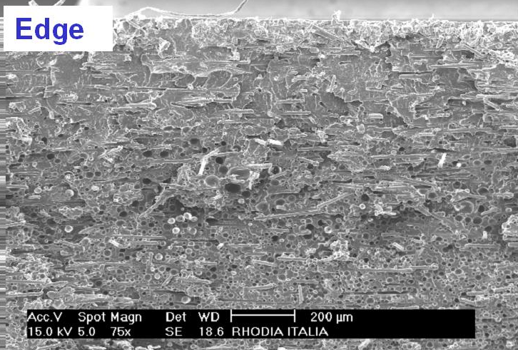
In fact, the material in the energy director for the PA 6 samples is completely free of cell structure. The thicker skin provides more material in the weld area and also in some instances, can move the cell structure completely out of the weld area.
Vibration Welding:
The vibration welding study was done using a bell mould. This mould produces a part such that two are put together to form a welded test specimen. The specimens were then tested for burst pressure.
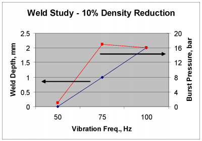
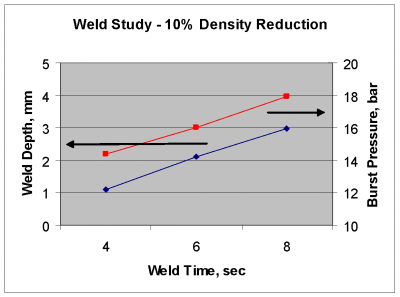
A short study was conducted to evaluate welding conditions and weld depth for parts produced with the MuCell process at 10% density reduction. It was found that the vibration frequency and weld time both contribute to the formation of a good weld. As vibration frequency was increased from 50 hz to 75 hz to 100 hz for a given weld time (6 seconds), the weld depth increased from no weld formation to 3 mm (graph 3). The increasing weld depth resulted in a stronger weld. It was also seen that for a given vibration frequency, in this case 100 hz, weld time effected the weld depth and therefore the weld strength (graph 4).
Graph 3 – Effect of Vibration Frequency
On PA 6.6
Graph 4 – Effect of Weld Time
On PA 6.6
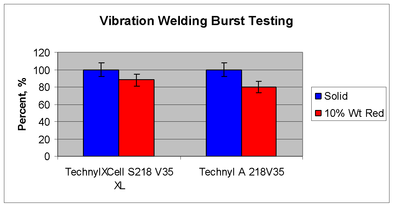
The results from the weld study were then used to set welding conditions for the MuCell samples for the burst testing comparison to solid samples. Using the optimized conditions, it was seen that the PA 6 samples have very little change between the solid parts and the 10% density reduced MuCell parts, a 12% decrease in burst pressure (Graph 5). The difference between the solid parts and the MuCell parts using the PA 6.6 at a 10% density reduction was 20%.
Graph 5 – Optimized Vibration Welding Study
Looking at the cell structure in the test parts, it was seen that cell structure was into the weld area with both materials. But that the cell size distribution was much better with the PA 6 than the PA 6.6. The cell structure for the PA 6 shows an average size below 20 mm and no cells greater than 50 microns. The maximum cell size for the PA 6.6 is 80 microns to 100 microns. This seems to indicate maximum cell size in the weld area is affecting the weld strength.
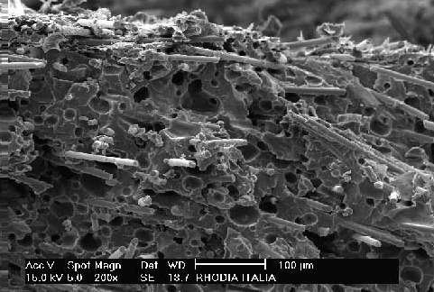
PA 6 Near Weld
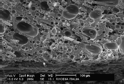
PA 6.6 Near Weld
In comparing the results of ultrasonic welding and vibration welding, it was seen that the MuCell samples compared more favorably to the solid samples when assembled by ultrasonic welding. A contributing factor is the energy director. The geometry of the energy director is such that there will be very little cell structure in this area and when properly designed, the energy directly should represent most of the material that is melted to form the weld in an ultrasonic welding process. Therefore, the material being melted to form the bond is free from cell structure.
In vibration welding, it is difficult to keep the cell structure from the weld area as these areas, by the nature of the process, are flat and relatively wide, 3 to 4 mm in width. However, cell structure control can be achieved through control of the SCF level, injection speed and also process temperatures. While different grades of PA 6 and 6.6 will react differently to the microcellular foaming process, this typically means nitrogen levels of 0.2 to 0.3% with higher injection speeds, above 50 mm/s. Glass fibre filled materials also tend to provide better cell structure than glass and mineral filled materials.
CONCLUSION:
Microcellular foam injection moulding is no longer just a development program. Numerous under the hood applications in glass fibre filled PA 6 and PA 6.6 are commercializing. Some of these applications require either ultrasonic or vibration welding processes to join parts in the final assembly. The work done here looks at the effect of the MuCell process on the welding process and weld strength. The results show that for a 10% density reduction in the microcellular moulded samples:
- It is possible to achieve similar burst pressure results between solid parts and microcellular foamed parts using ultrasonic welding with PA 6
- This is about a 12% decrease in the strength of an ultrasonic weld with PA 6.6.
- The drop in burst pressure strength for vibration welded assemblies using solid parts as compared to 10% density reduced MuCell parts is larger than for ultrasonic welded samples, 12% for PA 6 and 20% for PA 6.6
- Welding conditions do need to be optimized for microcellular foamed parts. An initial study showed that welding time and vibration frequency had significant effects on vibration weld strength.
- Skin thickness and cell structure in the weld areas effects the weld strength. The greater retention of weld strength with ultrasonically welded MuCell parts reflects the lack of cell structure in the energy director. SCF level and injection speed are two contributing factors to cell size.


